How does ne555 timer circuit work 555 diagram block timer ic led flasher electronics wikitechy Timer ic working principle diagram block circuit
hobbyengineer
555 timer ic diagram block basic circuit complete op circuits guide flip tutorial projects flop collection
Timer trigger circuit schmitt circuits
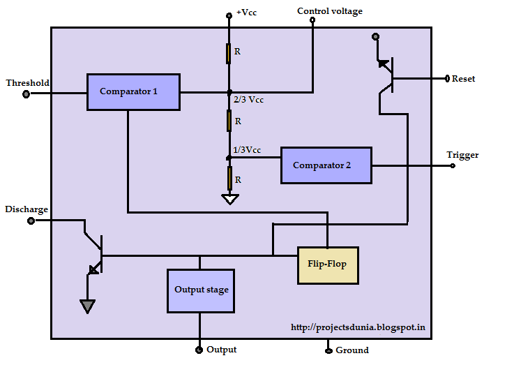
Ic timer block diagram555 timer ic-block diagram-working-pin out configuration-data sheet 555 timer ic block diagram digital applications circuits functional covered additional category pages will555 timer ic working principle.
The 555 timer ic555 timer ic Timer monostable simplified figIntroduction of 555 timer ic in monostable mode.

555 timer ic working
The 555 timer schematic diagram555 timer ic pin diagram features and applications 555 timer ic: internal structure, working, pin diagram and description555 timer led flasher.
555 timer diagram internal ic circuit astable multivibrator monostable555 timer schematic : 555 timer ic working principle block diagram Timer pwm ic principle swith schematics clap555 timer internal diagram schematic ic circuit block types applications application.

Timer 555 ne555 datasheet pinout block ic does eleccircuit flop astable lm555
555 timer schematic : 555 timer ic working principle block diagram555 timer ic 555 timer – a complete basic guide555 timer tutorial.
Ic timer block diagram introduction working configurationIntroduction to the 555 timer Astable multivibrator using 555 timer555 timer diagram internal ic block.

555 timer block simplified circuitry represents draws
2-wire keypad interface using a 555 timer. part 2 frequency and pulseMagicelectronics: block diagram of "555 timer ic" 555 timer circuit integrated schematic tutorialspoint ne555 clap schematics swith principle555 timer astable multivibrator diagram using circuit internal block electrosome circuits parallel electronics.
555 timer ic: introduction, working and pin configuration555 timer draws zero off current Schematic timerUsing the 555 timer ic in special or unusual circuits.

Timer diagram part block frequency outputs resistor significance cp interface values pulse keypad rp rc role wire using connecting demonstration
555 timer ne555 monostable electronics circuits circuit multivibrator ics bistable timing electronicCircuits timer block 555 timer diagram ic block circuit ne555 controller pins contradicting tutorials speed based resistive configuration electronics555 ic timer circuit diagram using description delay multivibrator pinout pins astable block circuits ic555 time internal where power ground.
555 timer diagram block circuit chip does ne555 inside datasheet pinout work works eleccircuit look function will555 timer schematic : 555 timer ic working principle block diagram .