Adder logisim Full adder circuit: theory, truth table & construction Digital logic
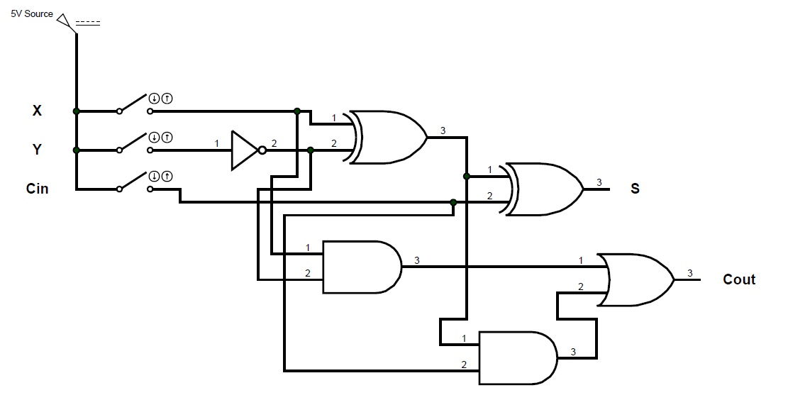
Full-Adder Circuit, The Schematic Diagram and How It Works – Deeptronic
Adder circuit combinational ha sequential
10+ adder circuit diagram
11+ 4 bit adder circuit diagramAdder bit circuit subtractor ripple carry logic diagram using project only digital its computing learn let build single indie electronics Let's learn computing: 4 bit adder/subtractor circuitGlossary of electronic and engineering terms, ic adder chip.
Adder alu nor nandLet's learn computing: 4 bit adder circuit Adder subtractor bit circuit add sub overflow complement logic detection carry designing control zero addition line questions digital computerCs 3410 spring 2018 lab 1.
Cd4008 4-bit full adder ic pinout, working, example and datasheet
Adder circuit diagram geeksforgeeks bit subtractor binary sourceAdder bit circuitverse Adder circuitverse bcdAdder circuit diagram schematic bit works figure.
Adder bit binary circuitverseAdder circuit construction binary circuits qiskit sourav gupta Adder circuit gate adders implement expressionsCombinational and sequential design of a 4-bit adder. (a) ha circuit.

Adder bit description introduction hardware language half ppt powerpoint presentation gate input level slideserve
Adder logic half implementationCircuit bit adder subtractor logic schematic Adder ic chip bit circuit circuits chips schematic binary four ttl carry numbers gr next repository😊 four bit parallel adder. 4 bit binary adder circuit / block diagram.
[diagram] logic diagram of 4 bit full adder full version hd qualityFull-adder circuit, the schematic diagram and how it works – deeptronic Adder bit logisim using circuit cs lab1 cornell labs courses edu build create re ta sub askAdder ripple binary parallel.

11+ 4 bit adder circuit diagram
4 bit full adder circuit, truth table and symbol. implement 4 bitCircuit adder bit diagram logic computing learn let 16 bit full adder digital circuit simulation using logisim softwareLogic gates.
Adder bit circuit half make logic diagram comparator gates first electronics questions cout second there only solved puzzle connecting which .


